'%3e%3cpath%20d='M19.3359%2018.2109L14.7344%2013.6094C15.875%2012.2188%2016.5625%2010.4375%2016.5625%208.49609C16.5625%204.04297%2012.9492%200.429688%208.49609%200.429688C4.03906%200.429688%200.429688%204.04297%200.429688%208.49609C0.429688%2012.9492%204.03906%2016.5625%208.49609%2016.5625C10.4375%2016.5625%2012.2148%2015.8789%2013.6055%2014.7383L18.207%2019.3359C18.5195%2019.6484%2019.0234%2019.6484%2019.3359%2019.3359C19.6484%2019.0273%2019.6484%2018.5195%2019.3359%2018.2109ZM8.49609%2014.957C4.92969%2014.957%202.03125%2012.0586%202.03125%208.49609C2.03125%204.93359%204.92969%202.03125%208.49609%202.03125C12.0586%202.03125%2014.9609%204.93359%2014.9609%208.49609C14.9609%2012.0586%2012.0586%2014.957%208.49609%2014.957Z'%20fill='%23535B62'/%3e%3c/g%3e%3cdefs%3e%3cclipPath%20id='clip0_12799_29299'%3e%3crect%20width='20'%20height='20'%20fill='white'/%3e%3c/clipPath%3e%3c/defs%3e%3c/svg%3e)

IGES vs. STEP: Which CAD File Format Should You Use?
Anyone who's worked with legacy CAD data long enough has run into an IGES file that "almost" imports correctly, until a surface gap shows up where two faces don't quite meet, and what should have been a clean solid turns into a repair job. That single issue is really the story of why STEP exists at all, and understanding it makes the difference between choosing a file format out of habit and choosing one that actually fits the handoff you're doing.
What Is IGES?
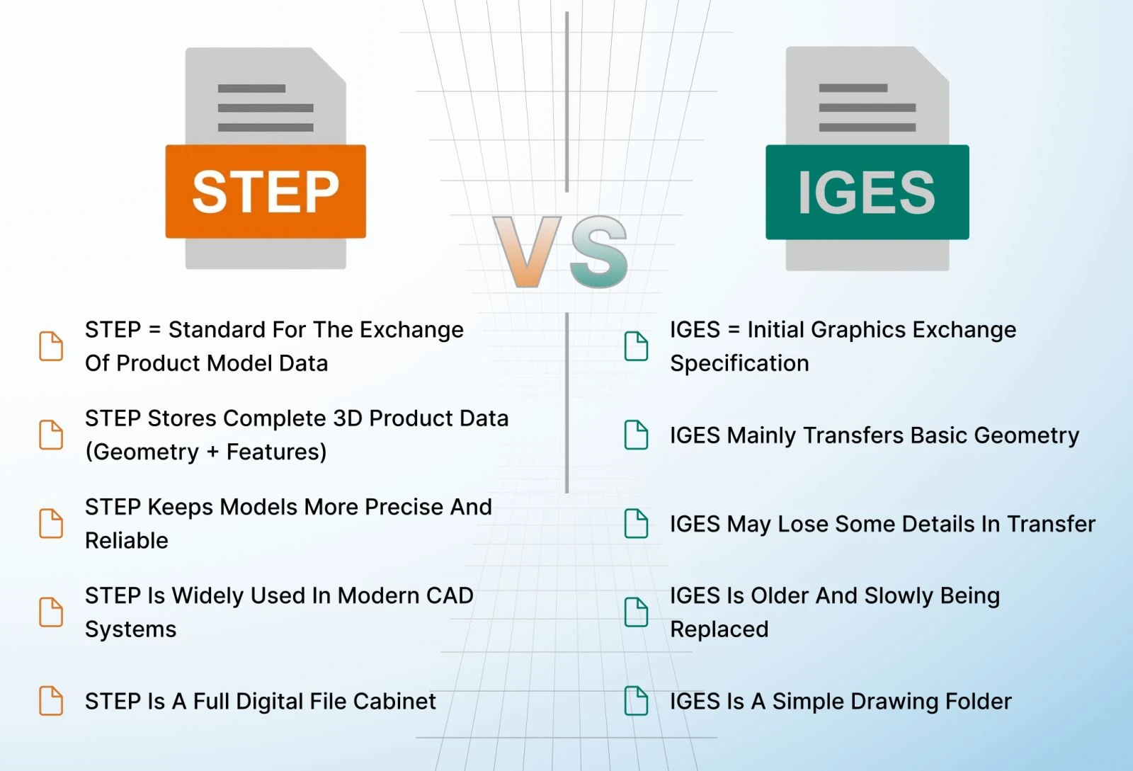
IGES, the Initial Graphics Exchange Specification, is one of the oldest neutral CAD file formats still in use today, first published around 1980 under the National Bureau of Standards and later maintained by the US Product Data Association. The final version, IGES 5.3, was published in 1996 and has remained essentially frozen since.
IGES was built for an era when solid modeling wasn't yet the industry default. Because of that, it represents geometry primarily as surfaces, trimmed surfaces, B-spline surfaces, and wireframe curves, rather than as a fully defined solid. This surface-based approach is exactly why IGES files are prone to the gap and overlap issues that CAD users still run into: without true solid topology tying every face together, a translated IGES model can end up with tiny leaks between surfaces that leave it technically not "watertight."
What Is STEP?
STEP, the STandard for the Exchange of Product model data, is the international standard (ISO 10303) developed specifically to solve the problems IGES couldn't. Unlike IGES, STEP represents geometry using proper boundary representation, or B-Rep, solid modeling, meaning a STEP file describes a fully enclosed, mathematically consistent volume rather than a loose collection of surfaces.
STEP is organized into different Application Protocols depending on what needs to be exchanged. AP203 covered basic mechanical parts and assemblies, AP214 added support for things like color, layers, and automotive-specific data, and AP242, the current and most capable protocol, merged the two and added robust support for product manufacturing information (PMI), the embedded dimensions, tolerances, and GD&T callouts used in model-based definition. STEP files also preserve assembly structure and part names far more reliably than IGES, making them the modern default for exchanging solid models between different CAD systems.
The Core Difference: Surfaces vs. Solids
The real distinction between IGES and STEP comes down to what each format was actually designed to represent. IGES describes a shape as a set of surfaces and curves, with no guarantee that those surfaces form a fully closed, valid solid. STEP describes a shape as a true solid, a fully bounded volume with consistent topology, which is why STEP-translated models are far less likely to require manual healing before they can be used for downstream engineering, machining, or 3D printing.
This isn't a minor technical footnote. A CAD import that isn't watertight can silently cause downstream problems: a CAM program that can't generate a valid toolpath, a simulation that fails to mesh properly, or a 3D print that fails because the slicer can't determine what's actually "inside" the part.
When to Use IGES
Despite its age, IGES still shows up in specific situations:
-
Working with older, archived CAD data from systems or projects that predate widespread STEP adoption
-
Legacy manufacturing or CNC toolchains that were built around IGES import decades ago and haven't been updated
-
Certain surface-heavy workflows, like Class-A automotive surfacing, where some older tools still default to IGES for that specific type of data
When to Use STEP
For nearly everything else in modern engineering, STEP is the better choice:
-
Exchanging solid models between different CAD platforms
-
Sending a design to a supplier or contract manufacturer for machining or tooling
-
Any workflow where assembly structure, part names, or PMI/GD&T data need to survive the handoff
-
Long-term archiving, since STEP is an actively maintained ISO standard rather than a format frozen since 1996
Where HVH Designer Fits
Choosing the right neutral format matters just as much as choosing the right CAD software to generate it. HVH Designer supports STEP export for reliable, watertight solid geometry, so models can move between engineering teams, suppliers, and other CAD systems without the surface-gap headaches that older formats like IGES can introduce.
As a browser-based CAD platform built on Parasolid-powered modeling, the same professional geometry kernel used across established commercial CAD systems, HVH Designer is built around producing clean, dependable solid geometry from the start, which matters just as much during file exchange as it does during initial design.
Conclusion
IGES and STEP were built to solve the same basic problem, moving CAD data between systems, but STEP was designed after the industry learned exactly where IGES fell short. Unless you're working with legacy data or a toolchain that specifically requires it, STEP's true solid modeling and broader metadata support make it the more reliable choice for nearly any modern CAD handoff.