'%3e%3cpath%20d='M19.3359%2018.2109L14.7344%2013.6094C15.875%2012.2188%2016.5625%2010.4375%2016.5625%208.49609C16.5625%204.04297%2012.9492%200.429688%208.49609%200.429688C4.03906%200.429688%200.429688%204.04297%200.429688%208.49609C0.429688%2012.9492%204.03906%2016.5625%208.49609%2016.5625C10.4375%2016.5625%2012.2148%2015.8789%2013.6055%2014.7383L18.207%2019.3359C18.5195%2019.6484%2019.0234%2019.6484%2019.3359%2019.3359C19.6484%2019.0273%2019.6484%2018.5195%2019.3359%2018.2109ZM8.49609%2014.957C4.92969%2014.957%202.03125%2012.0586%202.03125%208.49609C2.03125%204.93359%204.92969%202.03125%208.49609%202.03125C12.0586%202.03125%2014.9609%204.93359%2014.9609%208.49609C14.9609%2012.0586%2012.0586%2014.957%208.49609%2014.957Z'%20fill='%23535B62'/%3e%3c/g%3e%3cdefs%3e%3cclipPath%20id='clip0_12799_29299'%3e%3crect%20width='20'%20height='20'%20fill='white'/%3e%3c/clipPath%3e%3c/defs%3e%3c/svg%3e)

First Angle vs Third Angle Projection
Picture this: a supplier in Germany sends a drawing to a machine shop in the United States. The shop reads it, machines the part, and ships it back. Everything looks correct, except a key feature is on the wrong side. Nobody misread a dimension. They simply read the drawing using a different projection method.
First angle and third angle projection are the two standard ways of arranging views on an engineering drawing. They use the same views, but place them in different positions, and mixing them up can produce parts that are mirrored or unusable. In this guide, we'll explain how each method works, where it's used, how to recognize it, and why second and fourth angle projection exist in theory but never on the shop floor.
What Is Orthographic Projection?
Orthographic projection represents a 3D object as a set of 2D views, each looking straight at the object from one direction. The most common views are the front, top, and side, and together they describe the full shape and size of a part.
To understand projection angles, imagine two planes intersecting at right angles: a vertical plane (VP) and a horizontal plane (HP). Where they cross, they divide space into four quadrants:
-
First quadrant: above the HP and in front of the VP
-
Second quadrant: above the HP and behind the VP
-
Third quadrant: below the HP and behind the VP
-
Fourth quadrant: below the HP and in front of the VP
The observer always looks from the front and from above. The projection "angle" simply depends on which quadrant the object is placed in. After projecting the views onto the planes, the horizontal plane is rotated to lie flat with the vertical plane, producing the 2D layout you see on a drawing. The line where the two planes meet is called the reference line, or XY line.
What Is First Angle Projection?
In first angle projection, the object sits in the first quadrant, between the observer and the projection plane. Each view is projected through the object onto the plane behind it.
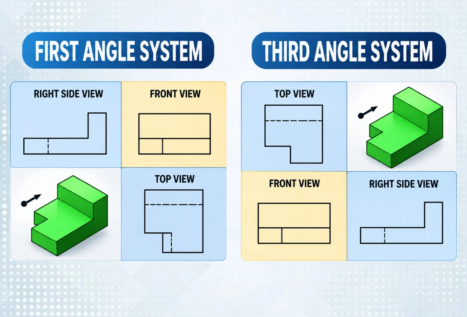
This creates a layout that can feel counterintuitive at first. With the front view as the reference:
-
The top view is placed below the front view
-
The bottom view is placed above the front view
-
The left side view is placed on the right
-
The right side view is placed on the left
A helpful way to picture it is to imagine rolling the object across the page. If you tip it forward to see its top, the top view lands below where the front was.
Where it's used: First angle projection is the standard across most of Europe, as well as in China, India, and much of Asia and Africa. It is the default method in ISO drawing standards.
What Is Third Angle Projection?
In third angle projection, the object sits in the third quadrant, with the projection plane between the observer and the object. Think of it as looking at the part through a transparent glass box and tracing each view onto the glass in front of you.
When the box is unfolded, each view ends up on the same side as the face it represents:
-
The top view is placed above the front view
-
The bottom view is placed below the front view
-
The right side view is placed on the right
-
The left side view is placed on the left
Many people find this layout more intuitive, since each view appears next to the side of the object it shows.
Where it's used: Third angle projection is the standard in the United States and Canada under ASME Y14 standards, and it's also widely used in Japan and Australia. The UK's BS 8888 standard permits both methods.
First Angle vs Third Angle Projection: The Key Differences
The two methods use the same views and the same geometry. The only difference is where those views are placed on the sheet.
In first angle projection, the object lies between the observer and the plane, so views are placed on the opposite side of the face they represent. In third angle projection, the plane lies between the observer and the object, so views are placed on the same side as the face they represent.
This is why a drawing read in the wrong projection can lead to a mirrored part. The views themselves look perfectly valid, so the mistake is easy to miss until the part fails inspection or doesn't fit its assembly.
How to Identify the Projection Symbol
Every professional engineering drawing should include a projection symbol, usually in or near the title block. The symbol shows a truncated cone in two views: a side view that looks like a trapezoid, and an end view that looks like two concentric circles.
In the first angle symbol, the circles appear to the right of the trapezoid. In the third angle symbol, the circles appear to the left of the trapezoid.
An easy way to remember it: in third angle projection, the view is placed on the side you're looking from. The circles show the cone viewed from its small end, which points left in the third angle symbol, so the circles appear on the left.
If a drawing has no projection symbol, check the applicable standard or the country of origin, and always confirm with the drawing's author before manufacturing.
What About Second and Fourth Angle Projection?
If there are four quadrants, why do we only hear about two projection methods? Second and fourth angle projection are theoretically possible, but they produce drawings that are practically unreadable.
Second Angle Projection
In second angle projection, the object is placed in the second quadrant, above the horizontal plane and behind the vertical plane. The front view is projected onto the VP and appears above the reference line. The top view is projected onto the HP, which sits behind the VP in this quadrant. When the HP is rotated into the plane of the drawing, that rear section swings upward, so the top view also lands above the reference line.
The result is that the front view and top view overlap, making the drawing confusing and difficult to interpret.
Fourth Angle Projection
In fourth angle projection, the object is placed in the fourth quadrant, below the horizontal plane and in front of the vertical plane. The front view appears below the reference line. The top view is projected onto the front section of the HP, which swings downward when rotated, so it also ends up below the reference line.
Once again, the front and top views overlap.
Why They Aren't Used
Both second and fourth angle projection place two principal views on top of each other, which defeats the purpose of orthographic drawing: clear, separate views that can be read without ambiguity. For this reason, no engineering standard uses them. They appear mainly in textbooks to help students understand why first and third angle became the accepted methods.
Which Projection Method Should You Use?
The right choice usually depends on your location, industry, and customers. If you work with ISO standards or European and Asian partners, first angle is typically expected. If you work with ASME standards or North American customers, third angle is the norm.
For companies working across borders, a few habits help avoid costly mistakes:
-
Always include the projection symbol on every drawing
-
Agree on a projection method with suppliers and customers at the start of a project
-
Train team members to read both methods, especially in global supply chains
-
Include an isometric or pictorial view when possible to confirm orientation at a glance
Projection Methods in CAD Software
Modern CAD software makes switching between projection methods easy. When creating 2D drawings from a 3D model, most platforms let you choose first or third angle in the drawing settings, and the views are arranged automatically. Because the drawing is generated directly from the 3D model, the geometry stays accurate no matter which layout you use.
Cloud-based CAD tools add another advantage for international teams: collaborators can open the original 3D model alongside the drawing, rotating and inspecting the part to confirm its orientation instead of relying on 2D views alone.
Frequently Asked Questions
What is the main difference between first angle and third angle projection?
The placement of views. In first angle, the top view goes below the front view; in third angle, it goes above.
Which countries use third angle projection?
Mainly the United States and Canada, along with Japan and Australia.
Which countries use first angle projection?
Most of Europe, as well as China, India, and many other countries following ISO standards.
Why are second and fourth angle projection not used?
Because the front and top views overlap, making the drawing unclear and difficult to read.
How can I tell which projection a drawing uses?
Look for the projection symbol in the title block. If the circles are to the right of the cone, it's first angle; if they're on the left, it's third angle.
Conclusion
First angle and third angle projection describe the same object in different layouts. First angle places views on the opposite side of the face they show and is standard in Europe and much of Asia, while third angle places views on the same side and is standard in North America. Second and fourth angle projection are theoretically possible but cause views to overlap, which is why no standard uses them.
Whichever method you work with, the projection symbol is your best defense against mirrored parts and costly rework. Check it on every drawing, and never assume.