'%3e%3cpath%20d='M19.3359%2018.2109L14.7344%2013.6094C15.875%2012.2188%2016.5625%2010.4375%2016.5625%208.49609C16.5625%204.04297%2012.9492%200.429688%208.49609%200.429688C4.03906%200.429688%200.429688%204.04297%200.429688%208.49609C0.429688%2012.9492%204.03906%2016.5625%208.49609%2016.5625C10.4375%2016.5625%2012.2148%2015.8789%2013.6055%2014.7383L18.207%2019.3359C18.5195%2019.6484%2019.0234%2019.6484%2019.3359%2019.3359C19.6484%2019.0273%2019.6484%2018.5195%2019.3359%2018.2109ZM8.49609%2014.957C4.92969%2014.957%202.03125%2012.0586%202.03125%208.49609C2.03125%204.93359%204.92969%202.03125%208.49609%202.03125C12.0586%202.03125%2014.9609%204.93359%2014.9609%208.49609C14.9609%2012.0586%2012.0586%2014.957%208.49609%2014.957Z'%20fill='%23535B62'/%3e%3c/g%3e%3cdefs%3e%3cclipPath%20id='clip0_12799_29299'%3e%3crect%20width='20'%20height='20'%20fill='white'/%3e%3c/clipPath%3e%3c/defs%3e%3c/svg%3e)

Geometric Dimensioning & Tolerancing (GD&T): A Complete Guide
Every manufactured part starts as a perfect idea. The challenge is turning that idea into a physical component that works reliably, repeatedly, and at scale. That is exactly what Geometric Dimensioning & Tolerancing (GD&T) is designed to solve. Far more than a set of symbols on a drawing, GD&T is the universal engineering language that connects design intent to manufacturing reality.
What Is GD&T?
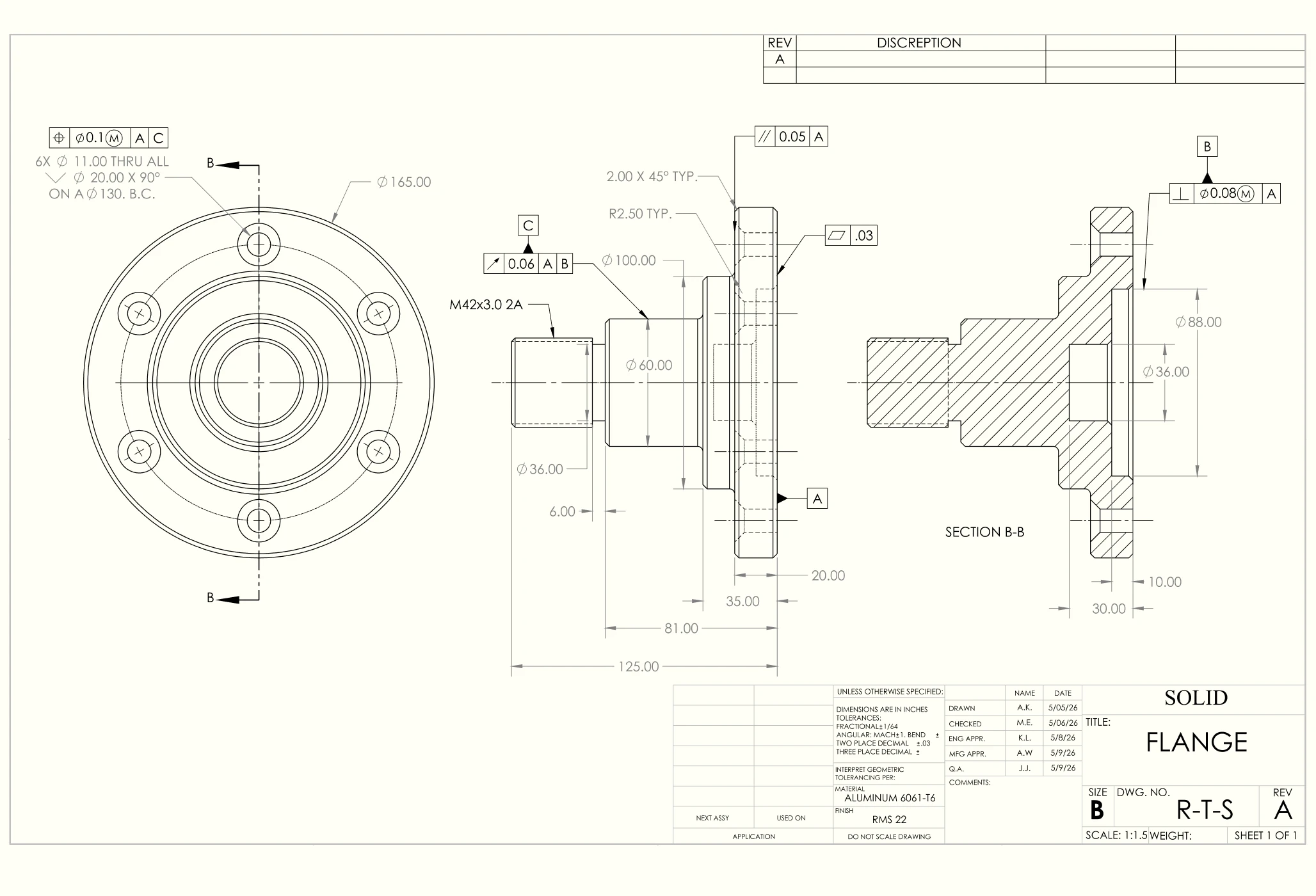
GD&T is a standardized system for defining and communicating engineering tolerances on technical drawings. Unlike traditional dimensioning, which only specifies size, GD&T defines shape, location, orientation, and runout, giving manufacturers a complete picture of what a finished part must look like geometrically. It ensures that design teams, manufacturers, and quality inspectors all share the same understanding, dramatically reducing the risk of miscommunication, scrap, and rework.
Two major standards govern GD&T globally: ASME Y14.5 (dominant in North America) and ISO GPS (widely used in Europe and international manufacturing). Both share the same core principles but differ in notation. Engineering teams must agree on which standard applies before a project begins.
Understanding Tolerances
A tolerance is the range within which a dimension can vary and still allow a part to function properly. Setting tolerances is a balance between precision and cost: tighter limits improve accuracy but increase production expense, while wider limits reduce cost but risk problems in assembly or performance. The objective is to provide enough flexibility to keep parts functional while maintaining competitive manufacturing costs and higher approval rates.
Geometric Characteristic Symbols
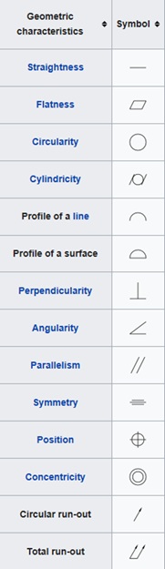
GD&T uses standardized symbols — the visual vocabulary of the system — grouped into five categories:
• Form: Straightness, Flatness, Circularity, Cylindricity
• Profile: Profile of a Line, Profile of a Surface
• Orientation: Perpendicularity, Angularity, Parallelism
• Location: Position, Concentricity, Symmetry
• Runout: Circular Runout, Total Runout
These symbols appear inside feature control frames — rectangular annotations on a drawing that specify the tolerance type, its value, and the datum references used for measurement. GD&T is a feature-based system: every symbol is applied to a specific surface, hole, or geometric element of the part.
Where GD&T Is Used
GD&T applies universally across manufacturing methods — CNC machining, injection molding, 3D printing, and sheet metal fabrication all rely on it. It is the backbone of precision industries including:
• Automotive: ensuring engine components, body panels, and transmission parts fit and function across global supply chains.
• Aerospace: specifying the ultra-tight tolerances required for aircraft and spacecraft components operating under extreme conditions.
• Medical Devices: defining the precise geometries required for surgical instruments and implants that interact directly with the human body.
Applying GD&T Effectively
Effective GD&T starts with understanding the function of each feature before assigning any tolerance. From there, select the appropriate geometric characteristic, define clear datums (reference points from which tolerances are measured), and use CAD software's built-in GD&T tools to annotate drawings accurately. Most importantly, ensure the entire team — design, manufacturing, and inspection — is trained to read and interpret the symbols consistently. GD&T is only as effective as the people using it.
Conclusion
GD&T is one of the most valuable tools in precision engineering. When applied correctly, it reduces scrap, eliminates rework, lowers costs, and ensures that every manufactured part functions exactly as designed. When misapplied or ignored it becomes a source of confusion, delays, and profit loss. Investing in GD&T knowledge is not just a technical upgrade; it is a direct investment in manufacturing quality and business performance.
For a detailed breakdown of the differences between STEP file formats and how AP203, AP214, and AP242 compare in practice, read our article on STEP File Formats: AP203, AP214 and AP242.