'%3e%3cpath%20d='M19.3359%2018.2109L14.7344%2013.6094C15.875%2012.2188%2016.5625%2010.4375%2016.5625%208.49609C16.5625%204.04297%2012.9492%200.429688%208.49609%200.429688C4.03906%200.429688%200.429688%204.04297%200.429688%208.49609C0.429688%2012.9492%204.03906%2016.5625%208.49609%2016.5625C10.4375%2016.5625%2012.2148%2015.8789%2013.6055%2014.7383L18.207%2019.3359C18.5195%2019.6484%2019.0234%2019.6484%2019.3359%2019.3359C19.6484%2019.0273%2019.6484%2018.5195%2019.3359%2018.2109ZM8.49609%2014.957C4.92969%2014.957%202.03125%2012.0586%202.03125%208.49609C2.03125%204.93359%204.92969%202.03125%208.49609%202.03125C12.0586%202.03125%2014.9609%204.93359%2014.9609%208.49609C14.9609%2012.0586%2012.0586%2014.957%208.49609%2014.957Z'%20fill='%23535B62'/%3e%3c/g%3e%3cdefs%3e%3cclipPath%20id='clip0_12799_29299'%3e%3crect%20width='20'%20height='20'%20fill='white'/%3e%3c/clipPath%3e%3c/defs%3e%3c/svg%3e)

Top-Down vs. Bottom-Up Assembly Design
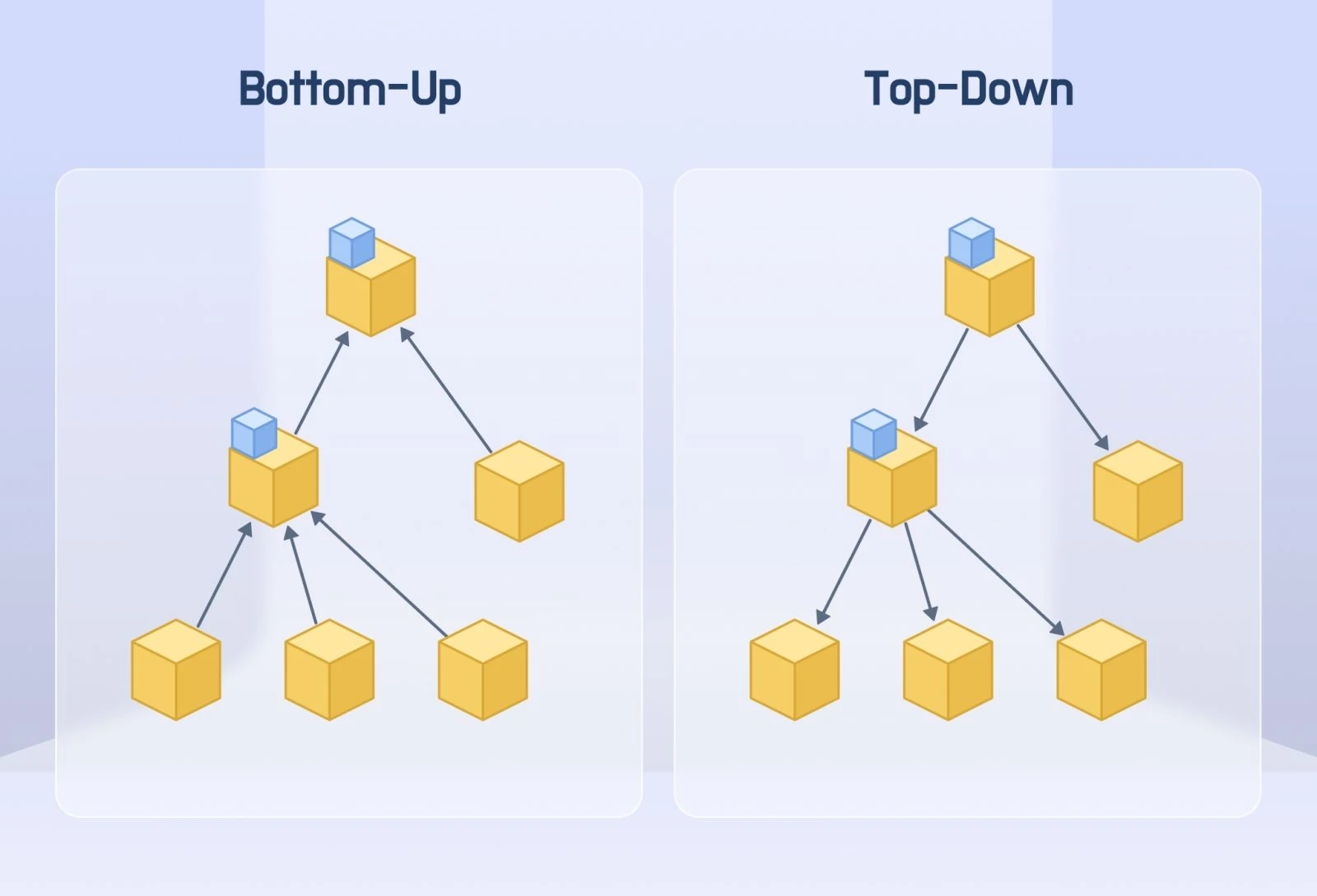
Every CAD assembly gets built one of two fundamental ways: parts first, or structure first. This choice, top-down versus bottom-up assembly design, shapes everything downstream: how easily the design accommodates change, how reusable individual parts are, and how much rework happens when a single dimension shifts late in a project.
Neither approach is universally correct. Understanding what each one actually does, and where it breaks down, is what separates a design that adapts gracefully to change from one that requires a rebuild every time the layout shifts.
What Is Bottom-Up Assembly Design?
Bottom-up design is the traditional, most widely taught approach to building CAD assemblies. Individual parts are modeled independently, each as a self-contained file with no knowledge of the assembly it will eventually belong to. Once the parts exist, they're brought together and constrained with mates or joints to form the finished assembly.
This mirrors how physical products have historically been built: a bracket, a shaft, a housing, and a fastener are each designed on their own, then assembled. Because each part file has no external dependencies, bottom-up parts are inherently portable. They can be reused across multiple assemblies, shared between engineers, and swapped out without dragging along a web of broken references.
Strengths of Bottom-Up Design
-
Reusability. A part designed once can be dropped into any number of future assemblies without modification.
-
Stability. Because parts don't reference each other's geometry, changes in one part rarely break another.
-
Natural fit for standard components. Bearings, fasteners, motors, and other off-the-shelf parts are inherently bottom-up. They already exist as complete, certified models before they ever touch an assembly.
Where Bottom-Up Falls Short
Bottom-up design struggles when parts are highly interdependent, when a bracket's mounting holes must align exactly with a motor that hasn't been finalized yet, for example. Without a shared reference driving both parts, engineers end up manually updating multiple files every time an interface dimension changes, which is slow and error-prone on complex assemblies.
What Is Top-Down Assembly Design?
Top-down design flips the sequence. Instead of starting with individual parts, the engineer first defines the overall structure, envelope, and key reference geometry of the assembly, often through a skeleton model or master layout sketch. Individual parts are then built in context, referencing that shared skeleton (or referencing each other directly) so that critical dimensions stay synchronized automatically.
If the skeleton defines a motor mount location and a shaft centerline, every part that depends on those references updates automatically when the skeleton changes. This makes top-down design especially powerful for capturing design intent in assemblies where the overall layout is still evolving, or where multiple interdependent parts must fit together with zero tolerance for misalignment.
Strengths of Top-Down Design
-
Synchronized changes. A single update to the skeleton propagates through every dependent part automatically.
-
Better for packaging-constrained designs. When overall envelope size or critical interfaces are dictated by external requirements, top-down design keeps every part honest to those constraints.
-
Clearer design intent. The relationships between parts are explicit and traceable, rather than coincidental.
Where Top-Down Falls Short
Top-down design introduces external references between files, links that, if not managed carefully, create fragile dependency chains. Move a file, rename a feature, or delete a referenced sketch, and downstream parts can break or fail to rebuild. Large assemblies built entirely top-down can also become slow to open and rebuild, since every part must resolve its references before the model is fully current.
The Hybrid Approach: What Most Real Assemblies Actually Use
In practice, very few production assemblies are purely top-down or purely bottom-up. Most engineering teams use a hybrid strategy: top-down skeleton modeling to lock down critical interfaces and overall envelope, combined with bottom-up modeling for everything that doesn't need to flex with the layout, especially standard, purchased, or previously validated components.
This is where a well-organized parts library becomes a genuine productivity advantage. Standard components like bearings, motors, couplings, and fasteners rarely need to be modeled in context; they need to be dropped in accurately and quickly. Platforms like HVH Designer support exactly this workflow, combining parametric modeling tools for building custom, top-down-driven geometry with an integrated 3D Parts Library of certified components from manufacturers like Rexnord, SKF, Flender, and Dodge Industrial. Instead of modeling a bearing from scratch to fit a top-down skeleton, engineers can pull in the real, manufacturer-accurate part and mate it directly to the skeleton reference, getting the reusability of bottom-up design without sacrificing the synchronized accuracy top-down design provides.
How to Decide Which Approach to Use
A few questions can guide the decision for any given assembly:
-
Are the parts interdependent, or largely independent? Interdependent interfaces favor top-down; independent components favor bottom-up.
-
Is the overall layout still changing? Evolving envelopes favor a top-down skeleton to avoid constant rework.
-
Are you using standard or purchased components? These almost always belong in a bottom-up workflow, since they already exist as finished parts.
-
How large is the assembly, and how sensitive is it to rebuild time? Very large assemblies benefit from limiting top-down references to only the most critical interfaces, keeping the rest bottom-up for stability and speed.
Conclusion
Top-down and bottom-up assembly design solve different problems. Bottom-up design rewards reusability and stability, making it the natural home for standard components and mature parts. Top-down design rewards synchronization and design intent, making it the right tool for evolving layouts and tightly interdependent geometry. Most well-built assemblies use both, applying top-down structure where accuracy across parts is critical, and bottom-up modeling everywhere else. Understanding which approach fits which part of your assembly, rather than defaulting to whichever method is more familiar, is what keeps a CAD project adaptable as it grows in complexity.