'%3e%3cpath%20d='M19.3359%2018.2109L14.7344%2013.6094C15.875%2012.2188%2016.5625%2010.4375%2016.5625%208.49609C16.5625%204.04297%2012.9492%200.429688%208.49609%200.429688C4.03906%200.429688%200.429688%204.04297%200.429688%208.49609C0.429688%2012.9492%204.03906%2016.5625%208.49609%2016.5625C10.4375%2016.5625%2012.2148%2015.8789%2013.6055%2014.7383L18.207%2019.3359C18.5195%2019.6484%2019.0234%2019.6484%2019.3359%2019.3359C19.6484%2019.0273%2019.6484%2018.5195%2019.3359%2018.2109ZM8.49609%2014.957C4.92969%2014.957%202.03125%2012.0586%202.03125%208.49609C2.03125%204.93359%204.92969%202.03125%208.49609%202.03125C12.0586%202.03125%2014.9609%204.93359%2014.9609%208.49609C14.9609%2012.0586%2012.0586%2014.957%208.49609%2014.957Z'%20fill='%23535B62'/%3e%3c/g%3e%3cdefs%3e%3cclipPath%20id='clip0_12799_29299'%3e%3crect%20width='20'%20height='20'%20fill='white'/%3e%3c/clipPath%3e%3c/defs%3e%3c/svg%3e)

Engineering Tolerances and Fits Explained
Every engineer eventually faces a simple-sounding question: how tight should these two parts fit together? A bearing that's too loose will spin on its shaft. A pin that's too tight might crack its housing during assembly. Somewhere between those extremes is the right fit, and finding it is one of the most practical skills in mechanical design.
In this guide, we'll break down engineering tolerances, explain the three main types of fits in engineering, walk through real ISO fit examples, and share tips for choosing the right fit for your design.
Why Engineering Tolerances Exist
No manufacturing process is perfect. If you machine a hundred shafts at 20 mm, each one will be slightly different, maybe a few microns over or under. Tolerances define how much variation is acceptable while still allowing the part to work.
Before diving into fits, it helps to know a few basic terms:
-
Nominal size (basic size): the target dimension, such as 20 mm
-
Upper limit and lower limit: the largest and smallest acceptable sizes
-
Tolerance: the difference between the upper and lower limits
-
Deviation: how far a limit sits from the nominal size
Tighter tolerances improve precision, but they also increase manufacturing cost. Good design means using tight tolerances only where the function demands them.
What Is a Fit in Engineering?
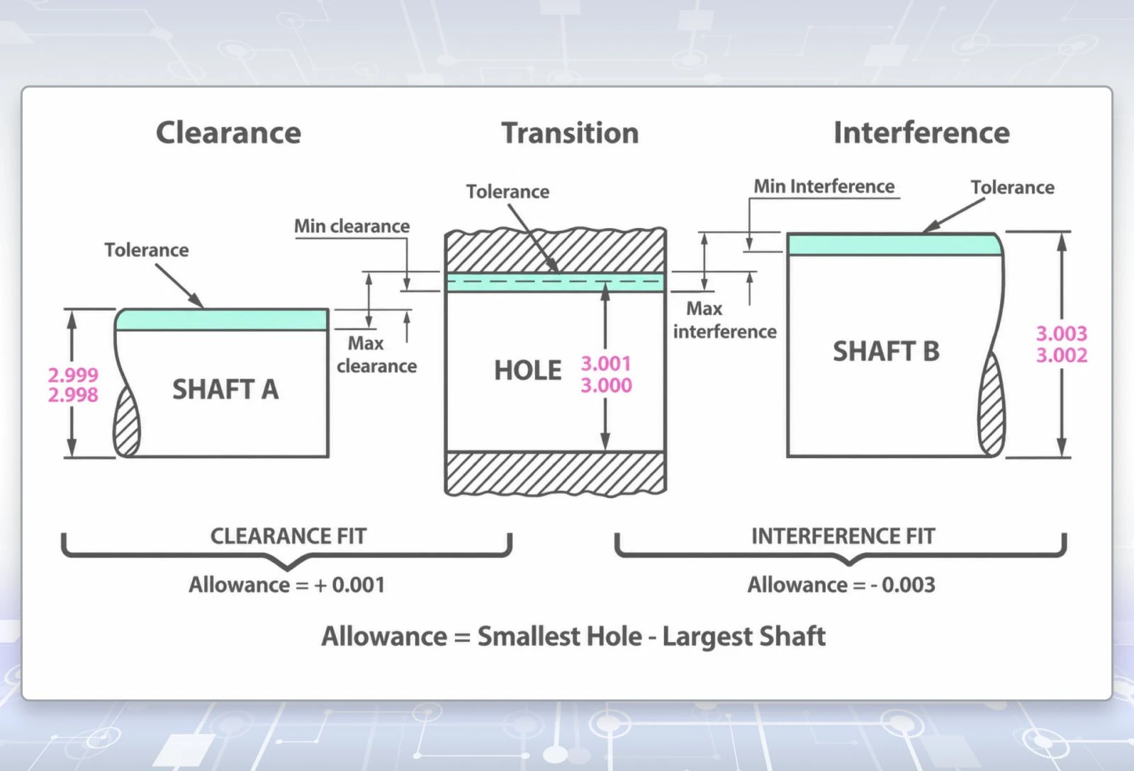
A fit describes the relationship between two mating parts, usually a shaft and a hole, once their tolerances are taken into account. Because both parts vary within their tolerance range, the fit is defined by the worst-case combinations: the loosest possible assembly and the tightest possible assembly.
Depending on those limits, the parts will either always have a gap, sometimes have a gap, or always overlap. That gives us the three types of fits in engineering.
1. Clearance Fit
A clearance fit always leaves a gap between the shaft and the hole. Even when the hole is at its smallest and the shaft is at its largest, the shaft still fits with room to spare.
This allows parts to slide or rotate freely, and they can be assembled and disassembled by hand.
Example: A 20 mm H7/g6 fit gives a clearance between 0.007 mm and 0.041 mm. The parts will always slide together, but with very little play.
Common clearance fits:
-
Loose running fit (H11/c11): generous clearance for rough conditions or where precision isn't important
-
Free running fit (H9/d9): for rotating parts at high speeds or with large temperature changes
-
Close running fit (H8/f7): for accurate running on machines with moderate speeds
-
Sliding fit (H7/g6): for parts that must move smoothly with minimal play
-
Locational clearance fit (H7/h6): for parts that need accurate positioning but can still be assembled freely
Typical applications: shafts in plain bearings, sliding gears, hinges, pivots, and guide pins.
2. Transition Fit
A transition fit sits between clearance and interference. Depending on where the actual sizes land within their tolerances, the assembly may have a tiny gap or a slight overlap.
Transition fits provide accurate location with very little movement, and parts usually need light pressure, a soft mallet, or a press to assemble.
Example: A 20 mm H7/k6 fit ranges from 0.019 mm of clearance to 0.015 mm of interference. Some assemblies will slide together, while others will need a gentle push.
Common transition fits:
-
Similar fit (H7/k6): accurate location with a choice between small clearance or small interference
-
Fixed fit (H7/n6): more precise location, where greater interference is acceptable
Typical applications: gears, pulleys, and couplings on shafts with keys, locating dowels, and bearing seats in certain housings.
3. Interference Fit
An interference fit means the shaft is always larger than the hole. Even at the loosest combination, the parts overlap, so they must be forced together.
Once assembled, friction between the surfaces holds the parts firmly in place, often strong enough to transmit torque without keys or fasteners.
Example: A 20 mm H7/p6 fit gives an interference between 0.001 mm and 0.035 mm.
Common interference fits:
-
Locational interference fit (H7/p6): rigid, accurate positioning with light interference
-
Medium drive fit (H7/s6): permanent assembly for steel parts or shrink fits on lighter sections
-
Force fit (H7/u6): high interference for parts under heavy loads, usually assembled by shrink fitting
Typical applications: bearings on rotating shafts, bushings in housings, gears and hubs, and wheel assemblies.
How Interference Fits Are Assembled
There are three main ways to assemble an interference fit:
-
Press fit: the shaft is forced into the hole using a hydraulic or arbor press
-
Shrink fit: the outer part is heated so it expands, then slipped over the shaft and allowed to cool
-
Expansion fit: the inner part is cooled, often with dry ice or liquid nitrogen, so it shrinks before insertion
Heating and cooling methods reduce the risk of scoring or damaging surfaces, especially with high interference values.
Hole Basis vs Shaft Basis System
There are two ways to build a system of fits.
In the hole basis system, the hole tolerance is fixed (usually H), and the shaft tolerance is changed to achieve the desired fit. This is by far the most common approach, because holes are made with standard drills, reamers, and gauges, while shafts are easier to machine to different sizes.
In the shaft basis system, the shaft tolerance is fixed (usually h), and the hole is adjusted instead. It's used when one shaft carries several components with different fits, or when using standard bar stock that's already ground to size.
In the US, the ANSI B4.1 standard uses a similar concept with fit classes such as RC (running and sliding), LC (locational clearance), LT (locational transition), LN (locational interference), and FN (force or shrink fits).
How to Choose the Right Fit
Choosing a fit starts with one question: what does this joint need to do?
-
Should the parts move relative to each other? Choose a clearance fit. The faster or hotter the motion, the more clearance you'll need.
-
Do the parts need accurate location but occasional disassembly? A transition fit is usually the right balance.
-
Must the parts stay locked together under load? An interference fit holds parts firmly without extra fasteners.
Beyond function, keep these factors in mind:
Thermal expansion: Parts made from different materials expand at different rates. A fit that works at room temperature may loosen or seize at operating temperature.
Material strength: Thin-walled or brittle parts may crack under high interference, so choose a lighter fit or a different assembly method.
Manufacturing cost: Tighter tolerances require more precise machining and inspection. Use precision only where it adds value.
Manufacturer recommendations: Bearings, bushings, and other standard components usually come with recommended shaft and housing fits. Always check the supplier's data first.
Common Mistakes to Avoid
Junior engineers often run into the same few problems when specifying fits. Using tight tolerances everywhere drives up cost without improving performance. Ignoring temperature effects can cause bearings to seize or press fits to loosen in service. Specifying a fit without considering how the parts will be assembled can make production difficult or impossible. And forgetting surface finish can undermine an otherwise correct fit, since rough surfaces flatten during assembly and reduce the effective interference.
Tolerances and Fits in CAD
In CAD, parts are typically modeled at their nominal size, and the fit is communicated through tolerances on the 2D drawing or as product manufacturing information (PMI) attached directly to the 3D model. Using ISO fit callouts like H7/g6 makes intent clear to manufacturers anywhere in the world.
Assembly modeling is also a great place to catch problems early. Checking clearances and interferences between mating parts helps confirm the design works before anything reaches the shop floor. In a browser-based CAD platforms you can build assemblies, bring in standard components from an integrated 3D library, and share the model with your team to review fits and clearances together.
Frequently Asked Questions
What are the three types of fits in engineering?
Clearance fit, transition fit, and interference fit.
What does H7/g6 mean?
It's an ISO fit where the hole has an H7 tolerance and the shaft has a g6 tolerance, producing a close sliding clearance fit.
What is the most common type of fit?
Clearance fits are the most common overall, with H7/g6 and H7/h6 widely used for precision assemblies.
What is the difference between a press fit and a shrink fit?
Both are interference fits. A press fit uses force to push parts together, while a shrink fit uses heat to expand the outer part before assembly.
Why is the hole basis system more common?
Because holes are made with standard tools like drills and reamers, it's easier and cheaper to keep the hole fixed and adjust the shaft.
Conclusion
Fits define how mating parts behave together. Clearance fits always leave a gap, so parts can slide or rotate. Transition fits may have a slight gap or slight overlap, giving accurate location with easy assembly. Interference fits always overlap, locking parts together through friction. By understanding ISO notation, choosing the right basis system, and matching the fit to the function, you'll design parts that assemble correctly, perform reliably, and stay cost-effective to manufacture.